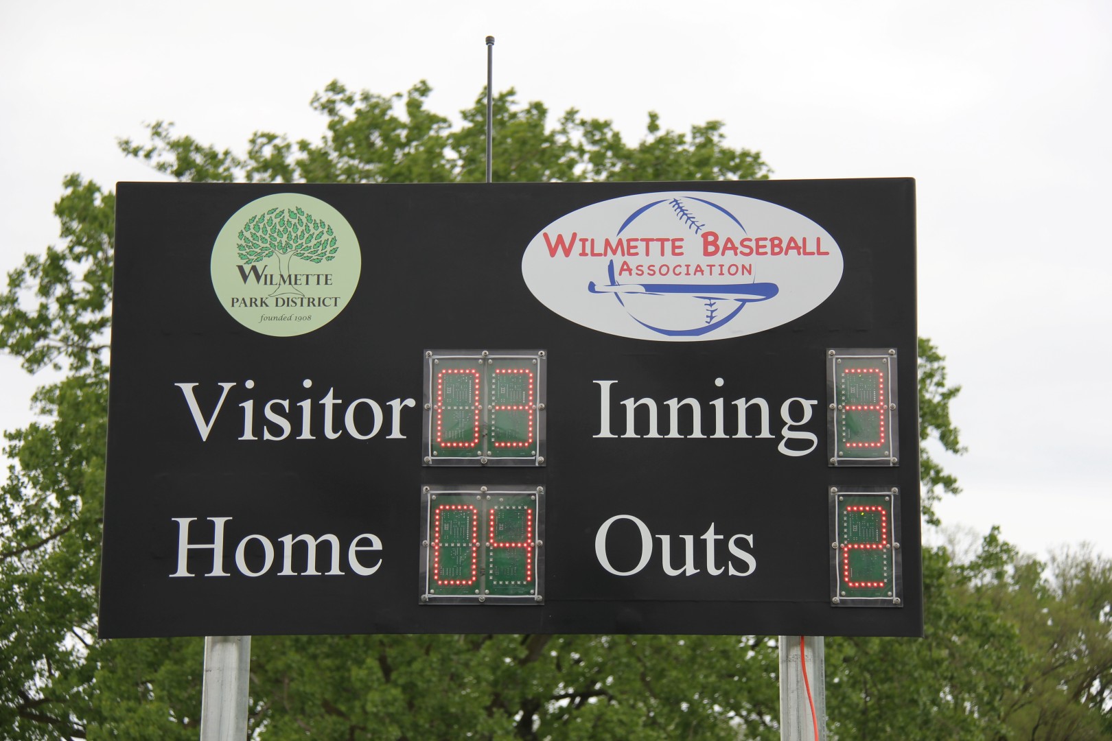
Baseball Scoreboard
Justin's Eagle Scout Project was this Scoreboard donated to the Wilmette Baseball Association and Wilmette Park District in Wilmette. It is located at the Wilmette Community Recreation Center Hibbard South Baseball Field. The Fourth Grade House and Travel Leagues play on this field.
Click Here for Scoreboard Construction Page
(Click on any picture to enlarge)
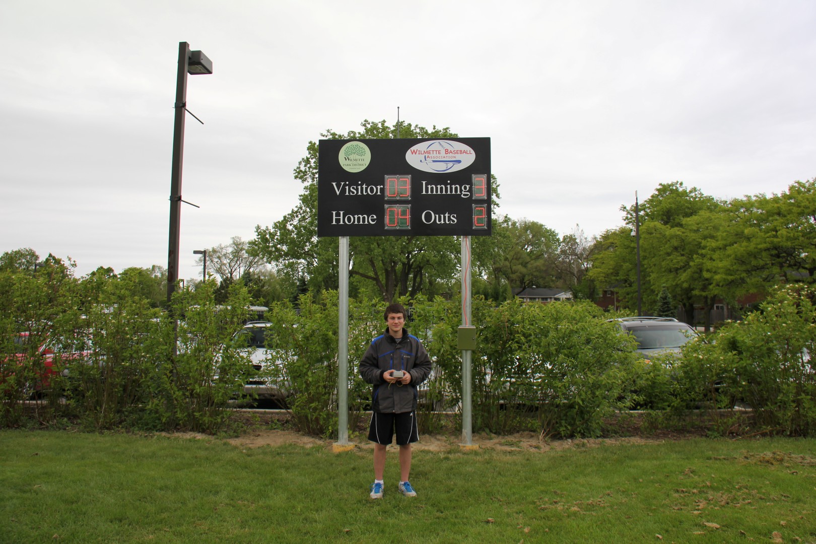
Justin with the Remote Control
Here is Justin holding the Remote Control unit. The Scoreboard is powered by 18 volts from 2 batterier (12 and 6 Volt in series) located in the battery box mounted on the right pipe support for the Scoreboard.
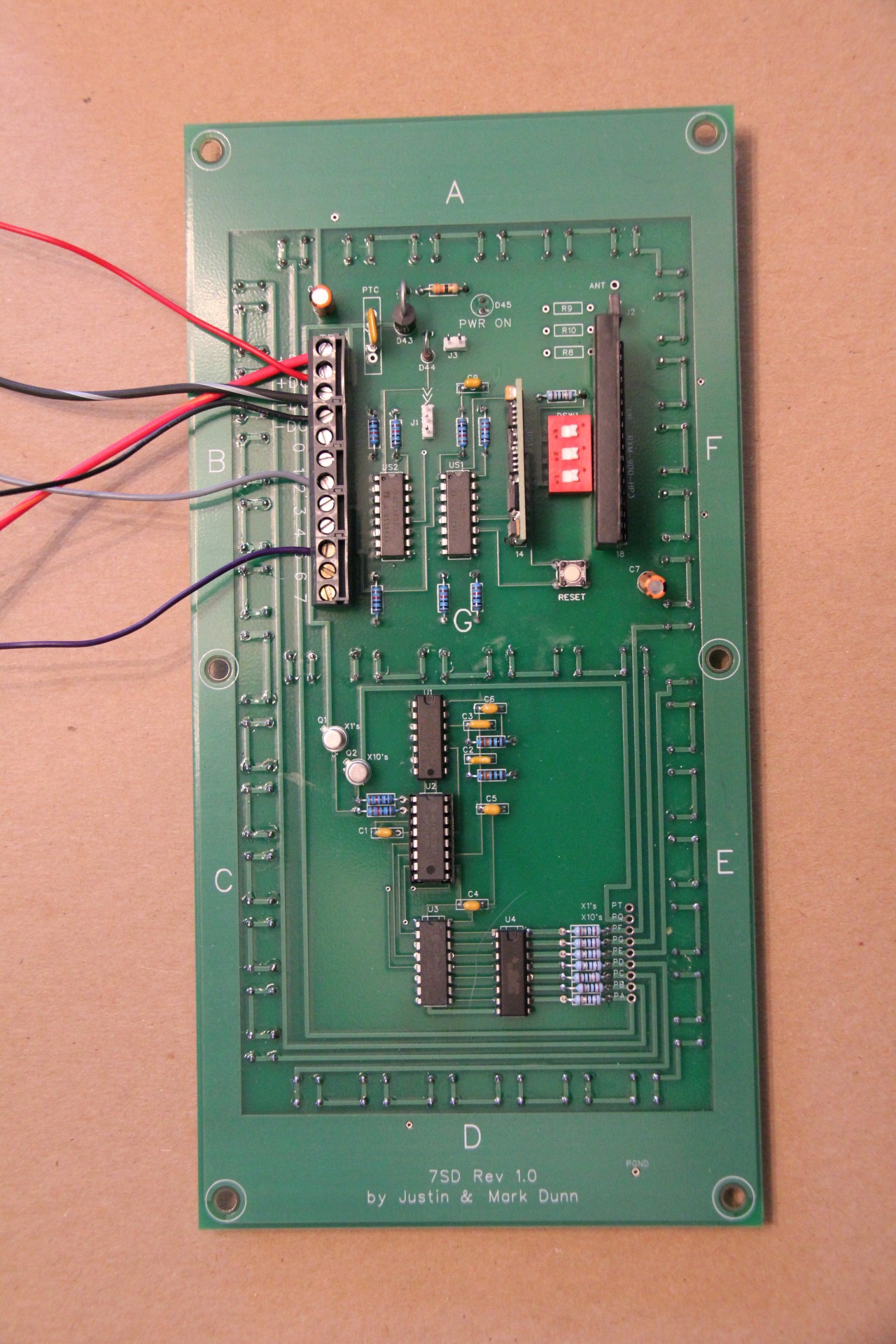
7 Segment Display
The Scoreboard Electronics consist of (6) Digits each of which is a PCB containing a 7 Segment Display. Each of the 7 Segments is made up of (6) High Current LED's in series for a total of (42) LED's. The 7 boards are identical in PCB construction, but different components are included or left off to give the correct functionality. This reduced the board cost as only one set-up was required to produce all of the boards.
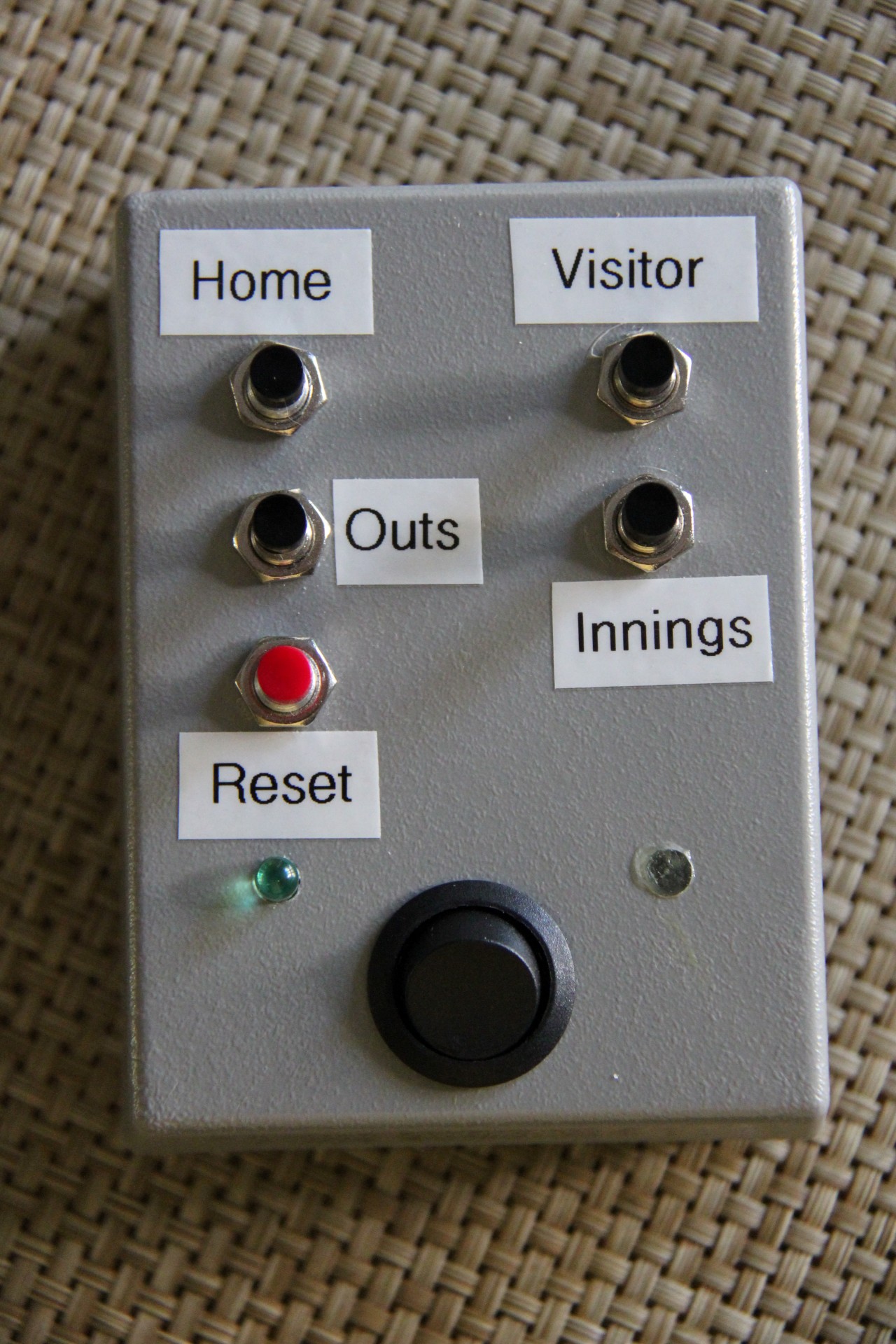
Remote Control Unit
The Remote Control Unit utilizes a Microcontroller to interpret the button presses. The Microcontroller sends an ASCII string to the RF Transmitter which operates at 903 mHz. Buttons are depressed to incremement Runs for the Home or Visiting Team, as well as Innings and Outs. Depressing the Reset button and the Home or Visitor button will reset the respective display to zero. The Outs automatically recycles to zero after displaying 3 Outs for a few seconds.
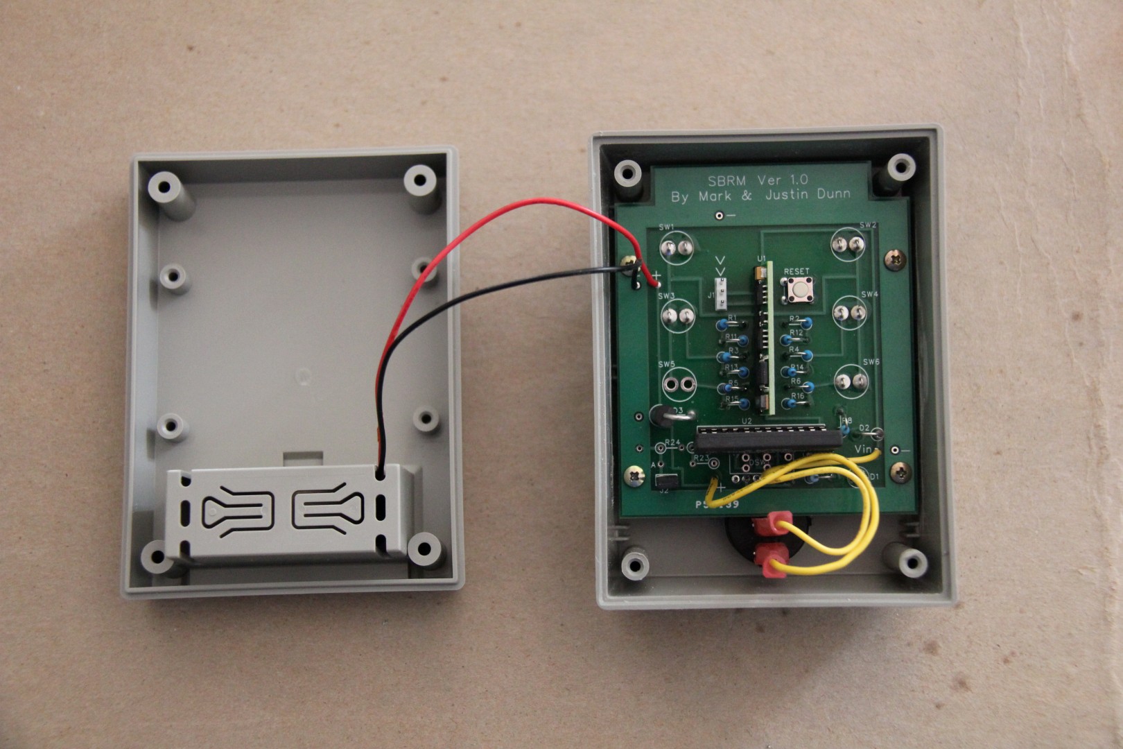
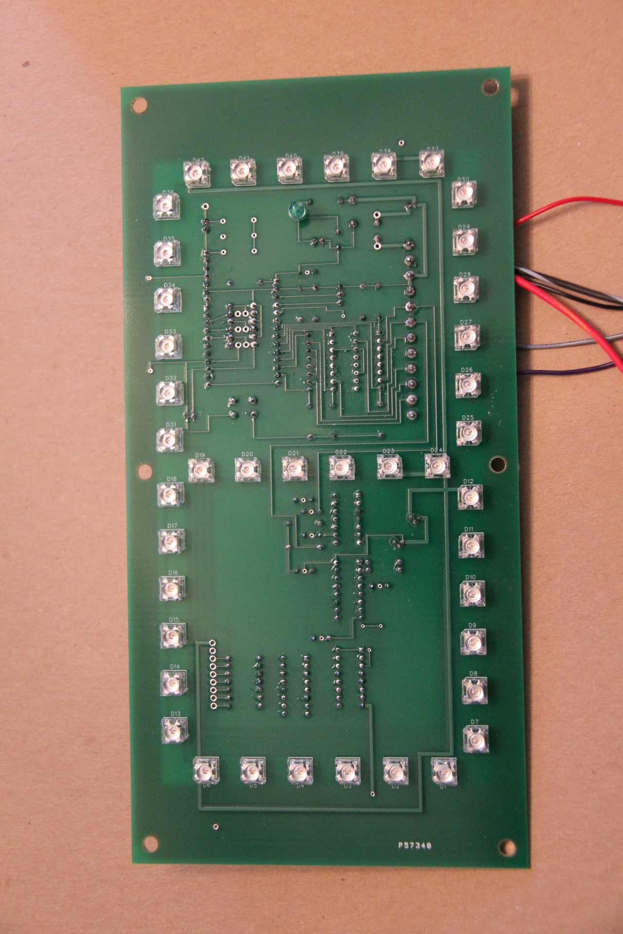
Remote PCB
Here is the board for the Remote Unit. It is powered from a 9 Volt Battery. The Microcontroller is mounted vertically in the center of the board and the RF Tranmitter Module is mounted horizontally along the bottom.
Main Controller Board & Home Display
This is the heart of the control. The RF Receiver Module receives the ASCII message and delivers it to a Microcontroller which interprets the command and increments the desired display. A BCD module drives a 7 segment display module which drives a darlington array (due to the high current requirement of the LEDs). Analog switches and a Schmidt Trigger are used to isolate the Microcontroller from the BCD module. The Microcontroller is located to the left of the red DIP Switch and the RF Receiver Module is located on the right. These components are mounted on the back of what is the Home Team Runs Display.
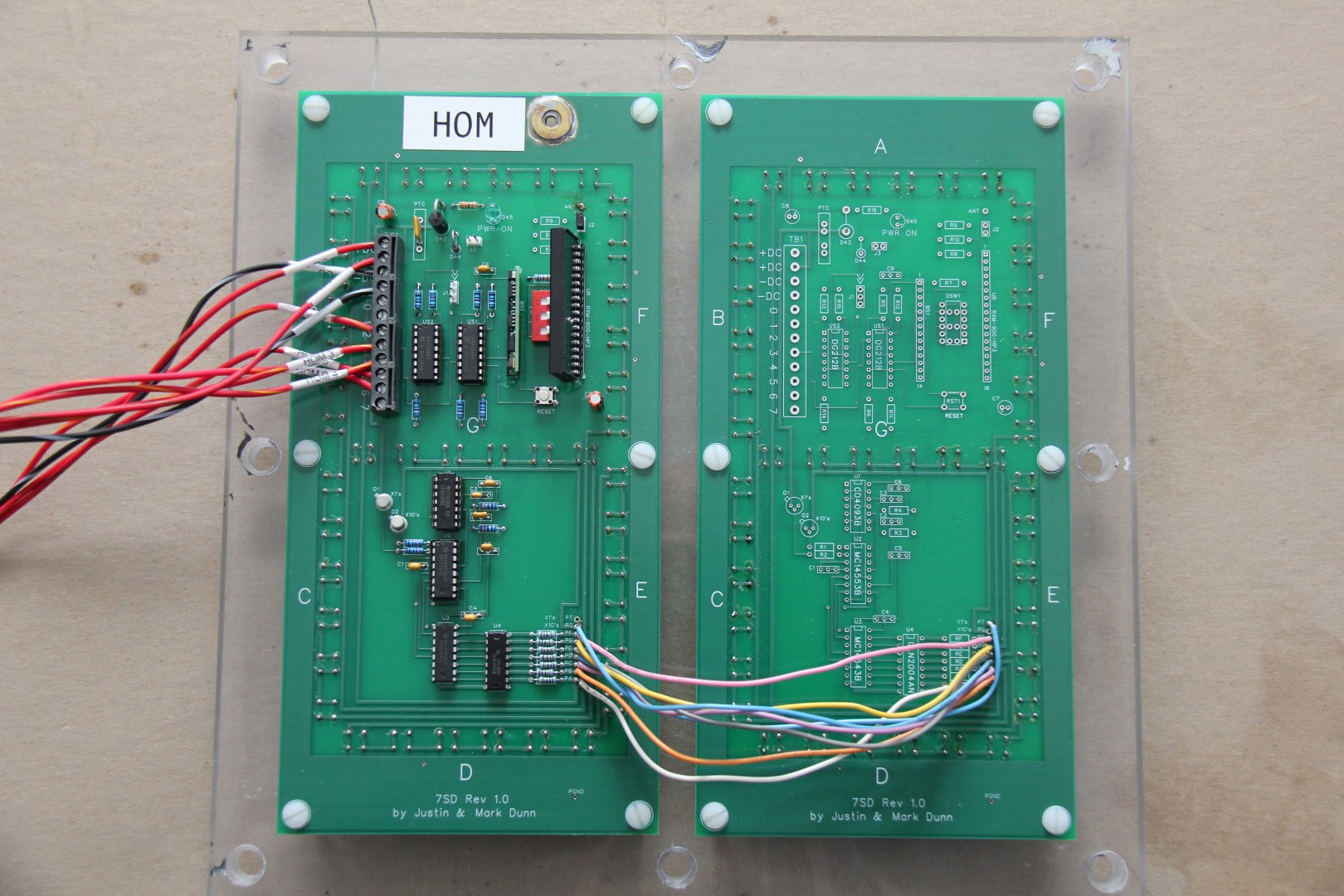
Home Display
The Home display is comprised of the Main Controller Board and a 2nd digit PCB so that the Runs digits can range from 0 99. The Main board diplays the 0's digit and the 2nd board the 10's digit. The 2nd digit is controlled by the BCD circuit on the Main board and wired directly as can be seen in the lower right of the picture.
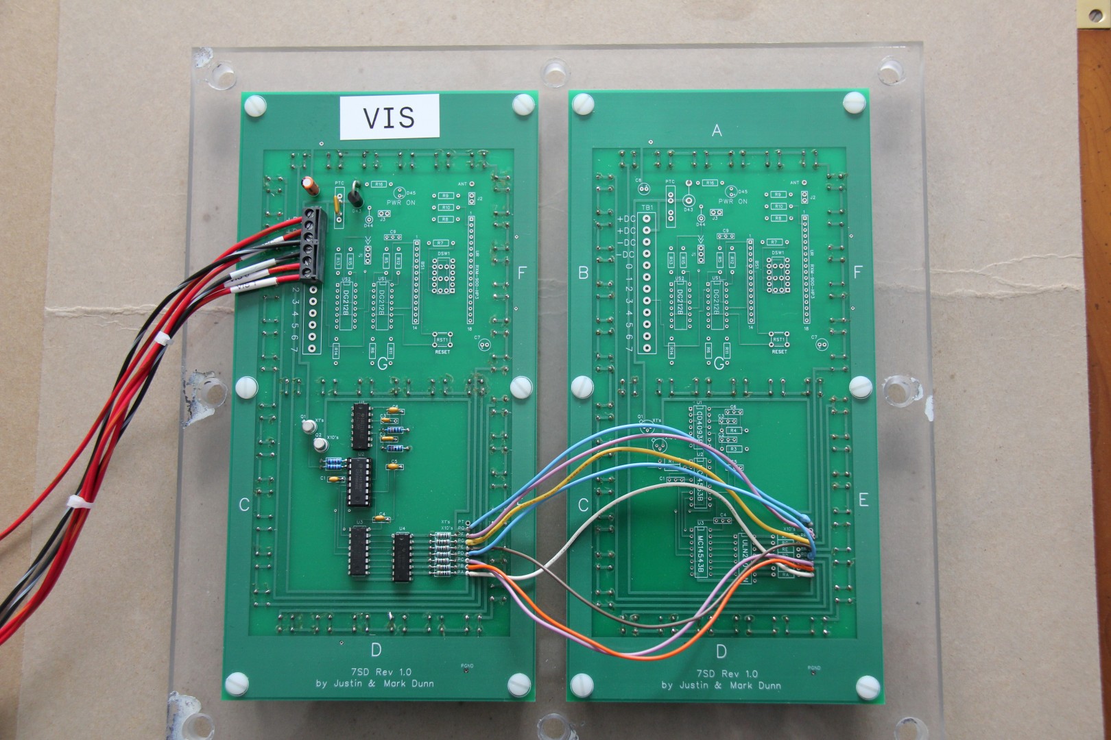
Visitor Display
The Visitor Display is also 2 digits. It only has the Schmidt Trigger, BCD, 7 Segment Driver, and Darlington Array. It receives the Increment and Reset commands via wire from the Main Controller Board.
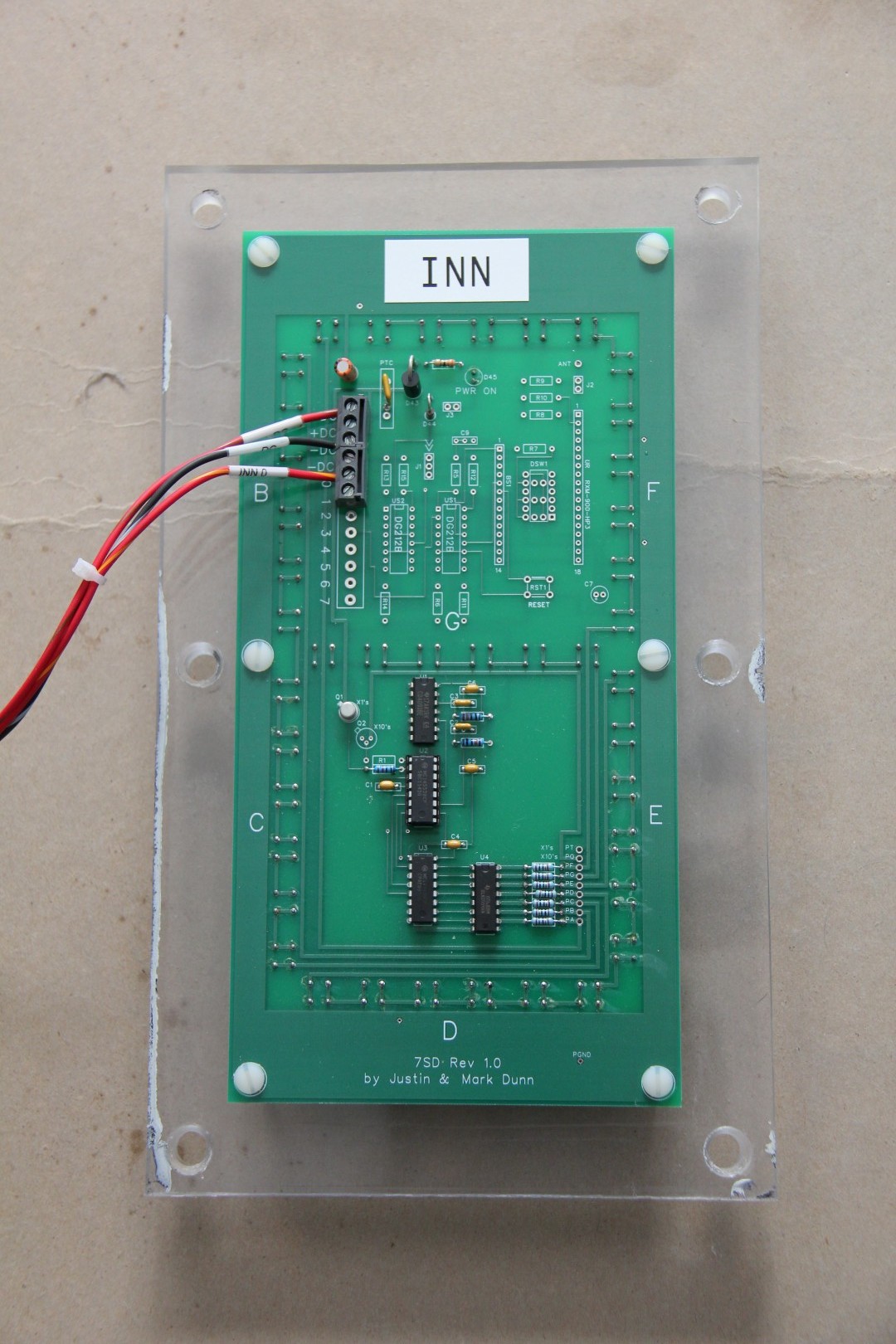
Innings Display
The Innings Display is a single digit. It requires the Schmidt Trigger, BC, 7 segment driver, and Darlington Array. It can only be Incremented and not Reset.
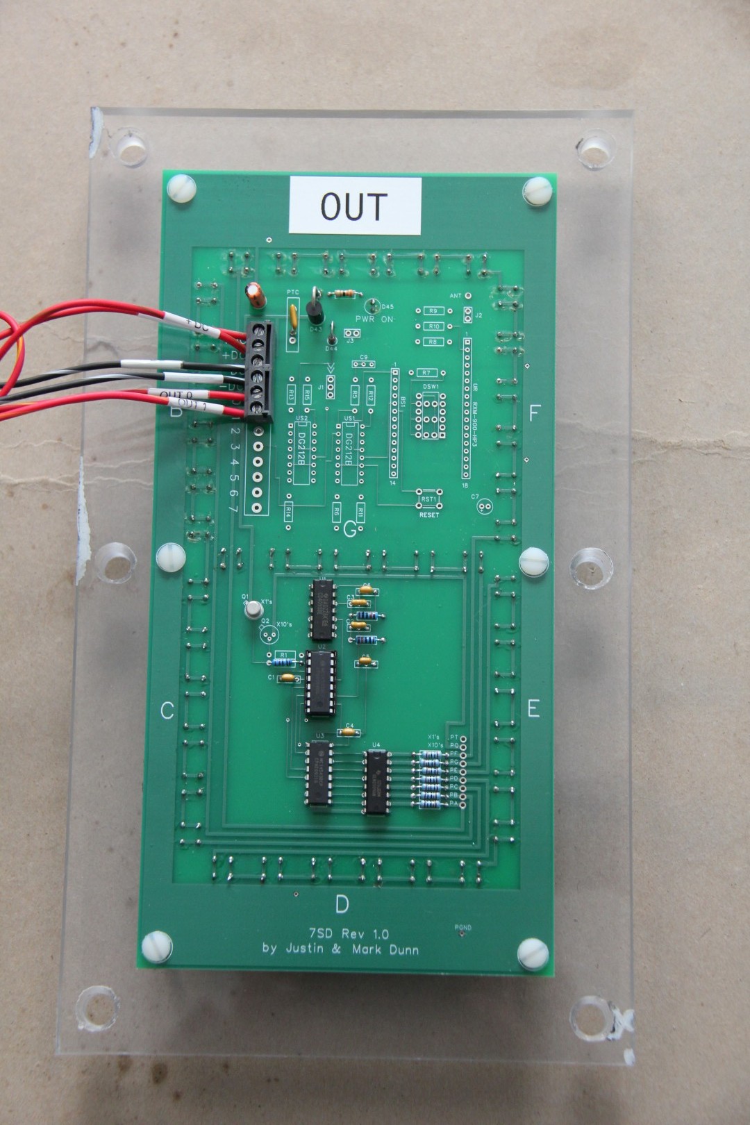
Outs Display
The Outs Display is similar to the Innings Display, but the Microcontroller is programmed to prevent it from displaying values greater than 3. When it reaches 3 Outs, it displays for a few seconds and then automatically Resets to 0.
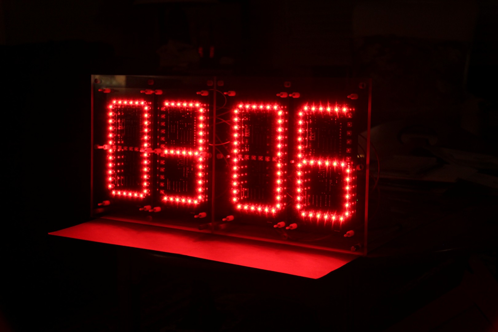
Demo
Here is a demonstration of the Home and Visitor Displays at home before they were installed in the Scoreboard. The LED's are extremely bright and can be seen at long distances.