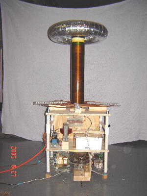
Tesla Coil
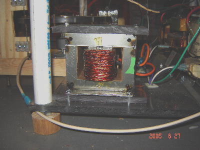
Here is our 2005 Tesla Coil project. It is a DC powered unit. Our configuration is built on three levels. The secondary(red vertical tube), toroid and primary are located on the top level. The tank capacitor, charging reactor, and Rectifier Board are on the middle level. The power transformers, current limiting inductor, and rotary spark gap are on the lower level.
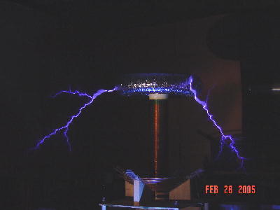
The coil resonates and 150 kHz and requires about 1500 watts of power. We achieve a first notch quench. Streamers are 48 to 60 inches in length.
Power Section
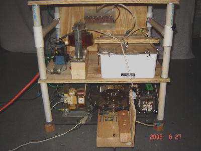
Here is a view of the lower sections. The 1st level contains the power transformers, current limiting inductor(on the far right), and spark gap(middle). A 12 volt contactor is located on the far left side of the 2nd level. The charging reactor is left of it and the tank capacitor on the right. Pictures and descriptions of the components follow.
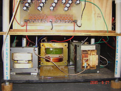
Power transformers
The transformers are (4) MOT's with the secondaries wired in series and a center tap to ground between the middle two. The transformer primaries on one side of the center tap are wired in parallel and the other two are wired anti-parallel. Each transformer has a turns ratio of approximately 17.5 so we get 4X17.5 = 70 times the voltage in the transformer secondary/primary.
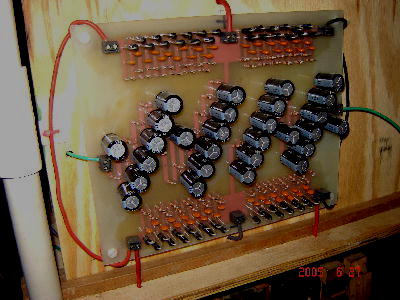
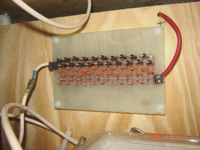
Full Bridge Rectifier
The Rectifier Bridge is made of (4) series of 1000 volt diodes with smoothing resistors and capacitors in parallel with each diode. Filter capacitors(with parallel bleed resistors for safety) are located on the DC side of the Rectifier Bridge to reduce ripple. Input to the board is 7000 VAC(3500 VAC to ground - 2 legs out of phase). Output from the board is +5000 VDC and -5000 VDC for a total of 10,000 VDC.
Current Limiting Inductor
The current limiter is #14ga wire wound on a gapped MOT core to get 15 mH. With this configuration we draw about 17 amps and the transformer primaries see approximately 100 Volts AC.
Charging Reactor
The charging reactor is 7500 turns of #30 ga wire on a pair of gapped U-100 cores. It has an inductance of 31 henries.
D-Q Diode
The diode was constructed from a series of 1000 Volt diodes with smoothing resistors and capacitors in parallel with each diode.
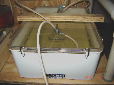
Tank Capacitor & Charging Circuit
The tank capacitor is an 38 nF parallel plate capacitor constructed from aluminum flashing for the conductor and polyester sheeting for the dielectric.
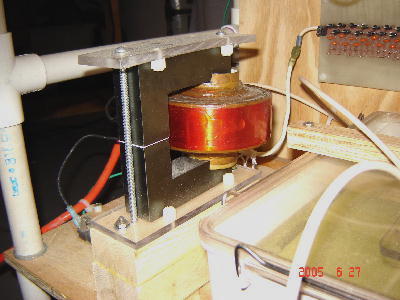
Tesla Secondary & Toroid
The Secondary is 4.5" Dia X 21" lg on a PVC Pipe(1290 turns of #27 ga wire). The toroid is made from 4"dia hose. It is 20" OD. The toroid is thus known as 4" X 20". The Toroid is wrapped in aluminum tape and has aluminum flashing cut in a circle and laminated to cardboard in the center for support.
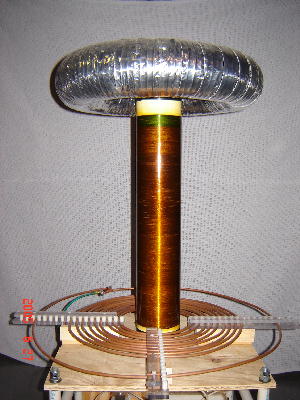
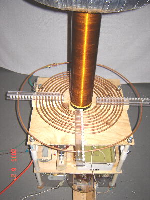
Tesla Primary & Strike Rail
The primary is 10 turns 1/4" copper tubing spaced 1/4" apart and mounted in a flat pancake configuration. It is tapped at 8 turns so that the primary circuit resonates at the same frequency as the secondary circuit. The outermost loop of tubing is the strike rail which is connected to RF ground and protects the primary from stikes.
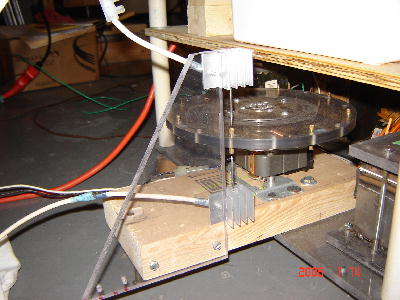
Rotary Spark Gap
The rotary spark gap consists of two tungsten electrodes. Brass screws mounted in a polycarbonate disc pass between the electrodes and close the circuit. The motor operates at 3200 RPM and there are 8 brass screws in the disc. This gives a spark gap break rate of 425 BPS.
Click Here to return to TeslaBoys Tesla Coil 2005 Page
Click Here to return to TeslaBoys Home Page