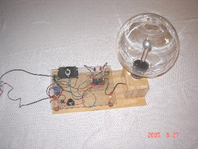
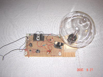
This is our 1st plasma globe power supply. It
uses a flyback from an old TV(pre-1970's) and a well known single or dual(push-pull)transistor circuit
with custom resistor choices to match the flyback and allow continuous
operation. The plasma globe is 12" diameter and contains a mixture of Neon, Xenon, and Krypton.
Click Here for Plasma Globe Driver Schematic*
* Viewing this gif file is poor on the Internet. Save to your computer and view with gif viewer.
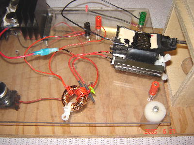
The resonant frequency of this flyback is 25 Khz and it generates approximately 25 Kvolts. The transistor is mounted on a heat sink. The circuit is powered with 12 vdc and a 40K uF capacitor is utilized as a filter cap to minimize ripple.
This is the flyback. It utilizes a gapped core made up of (2) U67/27/14 U-cores. Only the original secondary winding is used as seen on the left side of the picture. The primary and feedback windings are on the left side of the picture.
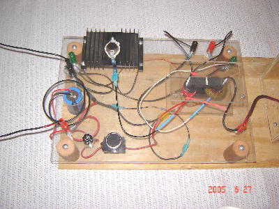
This power supply is similar to the first, but can utilize the
flyback from a recent TV set to power the globe. It can use a single or
dual transistor circuit as before. The 2nd transistor is shown, but
not being used at the time of the photo.
Click Here for 2nd Generation Plasma Globe Driver Schematic*
* Viewing this gif file is poor on the Internet. Save to your computer and view with gif viewer.
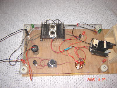
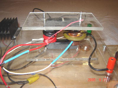
To make this power supply work, one places an intermediate transformer
between the circuit and the flyback. In this case, a toriodal core was used
with the primary and feedback windings on it. The toroid secondary is then connected
to the original primary of the flyback. This method steps up the circuit
voltage from 12 volts to approximately 100 volts to drive the flyback primary.
This method allows the transistor operate under conditions that it can survive.
Attempting to directly drive the flyback would destroy it.
The flyback has an internal
diode on the output which must be bypassed for this to work. You will note that
the side of the flyback has been ground away exposing the diodes for bypassing.
New MOSFET Driver Below ... Details to follow...
Click Here for MOSFET Driver Schematic*
* Viewing this gif file is poor on the Internet. Save to your computer and view with gif viewer.